This is a read-only snapshot of the ComputerCraft forums, taken in April 2020.
Andrew2060's profile picture

[Help] Drawing a rotating line.

Started by Andrew2060, 29 November 2015 - 08:26 AM
Andrew2060 #1
Posted 29 November 2015 - 09:26 AM
Hello!

Overview:
I am a okay leveled programmer and have basically been writing scripts for ICBM mod.
While doing so i discovered that the actual ICBM block radar doesn't display targets well.
So i decided to come up with my own CC interface that uses radar data to plot points.

Basically its supposed to make a circle that has a rotating line within it.
The actual radar look, (kind of like a fan with a slow single blade rotating).

The screen looks like the following right now:
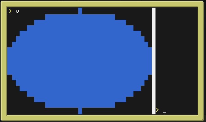

The circle is where points will be plotted and also where the line will rotate.
The white line on the right separates the radar from a list of incoming targets

My Actual Question:

I was wondering if anyone knew how to well do the following:

1. Plot points on the circle.
2. Have a white line rotate in the circle.

Program:
http://pastebin.com/TFZuGWYx

Many Thanks!!

~Andrew2060
Bomb Bloke #2
Posted 29 November 2015 - 11:19 AM
Regarding your line, there are three points of interest: the two points on the perimeter (opposite each other), and the center (which the other two rotate around).

Stealing some trig from here (so sue me, it's been a long time since college), and applying a bit of scaling / point translation to put it on a screen sorta like the one you've got there, and we get:

Spoiler
local radius = 50 -- Best make this match the range of your scanner, in blocks.

local p1 = {["x"] = -radius, ["y"] = 0}
local p2 = {["x"] =  radius, ["y"] = 0}

-- Rotate supplied point around an origin point of x0/y0:
local function getRotated(p, angle)
	angle = math.rad(angle)
	
	local sin = math.sin(angle)
	local cos = math.cos(angle)
	
	return {["x"] = p.x * cos - p.y * sin, ["y"] = p.x * sin + p.y * cos}
end

-- Shift points and scale to a 39x19 grid:
local function translate(p)
	return {["x"] = math.floor((p.x + radius) / (radius * 2) * 38) + 1, ["y"] = math.floor((p.y + radius) / (radius * 2) * 18) + 1}
end

local angle = 0

while true do
	local rp1 = translate(getRotated(p1, angle))
	local rp2 = translate(getRotated(p2, angle))
	
	term.setBackgroundColour(colours.black)
	term.clear()
	
	paintutils.drawLine(rp1.x, rp1.y, rp2.x, rp2.y, colours.white)
	
	angle = angle + 1
	if angle > 359 then angle = 0 end
	sleep(0.05)
end

In regards to the points your radar picks up, they should be easy to position: just run 'em through the translate function and dump them on the screen. If your sensor gets the co-ords as absolute values (as opposed to values relative to the sensor itself), then subtract the x/y co-ord of the sensor from the detected co-ords before passing them to the translate function.

If you really wanted to be fancy, you could calculate the angle between the sensor and anything it detects (floored for the sake of simplicity). If the angle of your line (or that angle + 180 degrees) matches that of one of your contacts, draw that contact as white on-screen. Run timers and have the points be re-drawn in light grey, then regular grey, and then finally black as they expire.
Andrew2060 #3
Posted 29 November 2015 - 11:34 AM
Wow nice!

Lol, It's a learning process for me, first comes practicality, then comes functionality then comes aesthetics.
But that is a pretty cool idea, having the "exhaust" of the line would give some pretty realistic look to it.

thanks for the help!